An electrocardiogram can show a dozen traces even though it uses only ten physical electrodes. The key is that an electrode is a contact point on the body, while a lead is a voltage difference measured or calculated from contact points. Each lead emphasizes the heart’s changing electrical field from a different direction. The familiar “views” are useful models of measurement geometry, not twelve separate recordings of twelve heart regions. [1]
A lead is a comparison, not a wire
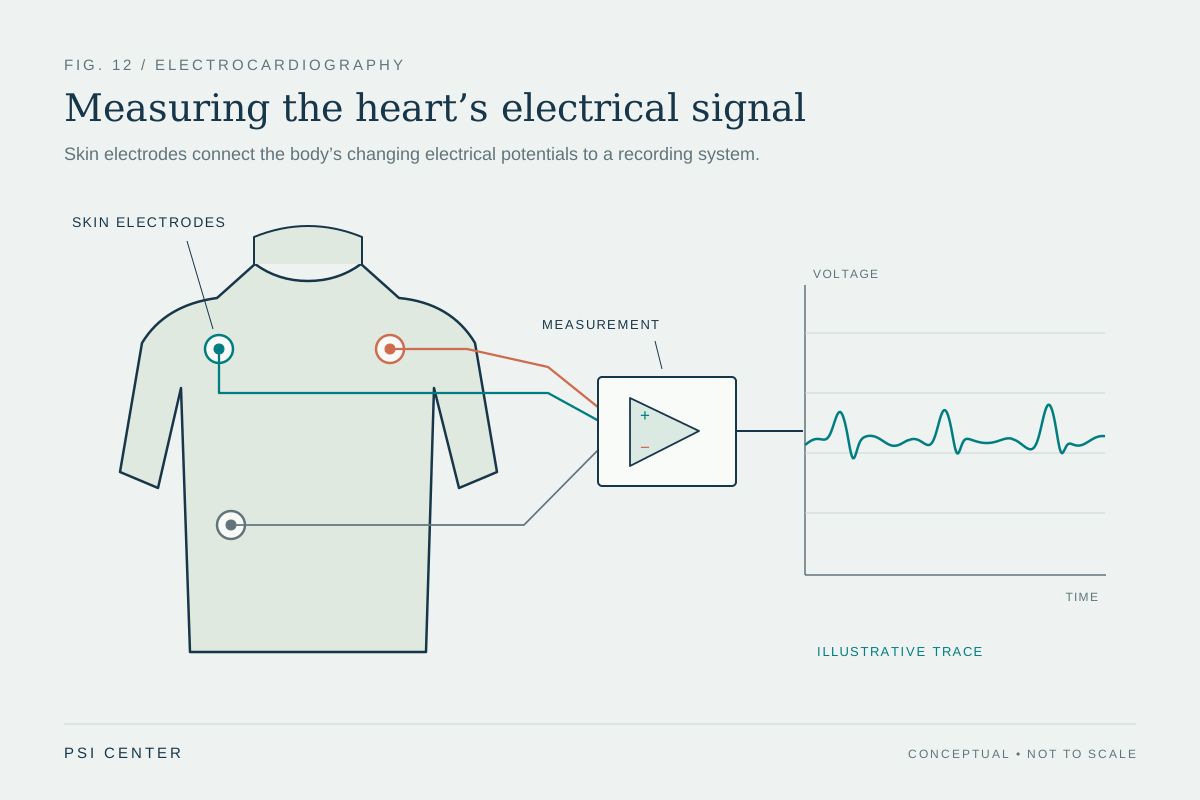
A skin electrode senses electrical potential at one location. An ECG channel compares potentials at two defined points or compares one point with a constructed reference. The machine displays that difference over time. Changing which points enter the comparison changes the lead, even if the heart’s electrical activity is identical. The distinction is similar to measuring elevation: a location has a height, but a reported height difference depends on which second location serves as the reference. [1]
The right leg electrode commonly helps the recording system manage electrical interference; it is not one of the standard limb leads. The limb leads instead use right arm (RA), left arm (LA), and left leg (LL) potentials to create three basic comparisons. A fourth point is not required to make a fourth independent cardiac viewpoint.
Three limb leads follow directly from the wiring
Lead I is LA minus RA, lead II is LL minus RA, and lead III is LL minus LA. These definitions produce Einthoven’s relationship: lead II equals lead I plus lead III. It is an algebraic consequence of subtracting the same electrode potentials, not a claim that the heart’s electrical field is a rigid arrow. [1]
For a deliberately simple example, suppose the three measured potentials at one instant are RA = −0.2 millivolts, LA = +0.3 millivolts, and LL = +0.6 millivolts. Then lead I is 0.5 mV, lead II is 0.8 mV, and lead III is 0.3 mV; 0.5 + 0.3 = 0.8. These invented values just demonstrate the arithmetic. Real recordings contain time-varying potentials shaped by the whole body and the measurement system.
Six limb leads add directions, not six new sensors
A standard 12-lead ECG contains three bipolar limb leads (I, II, III), three augmented limb leads (aVR, aVL, aVF), and six chest leads (V1–V6). The augmented limb leads compare one limb electrode with a reference calculated from the other two limb electrodes. The chest leads compare each chest electrode with the Wilson central terminal, a reference derived from the limb electrodes. In that sense, twelve named leads are constructed from ten physical electrodes. [1]
The six limb leads are conventionally arranged as directions in the frontal plane, while the chest leads sample voltage differences across positions on the front of the chest. The layout supports a richer description than one channel can provide. Yet each trace remains a projection of a distributed electrical process through a conductive torso, and neighboring lead views are mathematically related rather than fully independent.
A vector is a helpful approximation
For teaching, the combined electrical activity during part of a heartbeat is often represented as a changing vector. A lead oriented roughly along that vector tends to show a larger positive deflection; a lead oriented across it may show a smaller one, and a lead pointing the other way may show a negative deflection. This projection picture helps explain why waveforms differ across leads and why comparing leads can reveal spatial patterns. [1]
It is only an approximation. The heart is not a single point source, the torso is not a uniform conductor, and its geometry and tissues affect the potentials that reach the skin. The 12-lead ECG is therefore a standardized set of surface measurements, not a literal camera that isolates twelve anatomical slices.
Electrode position is part of the measurement
If a limb electrode is moved from a wrist or ankle onto the torso, the resulting lead vectors and voltage differences can change. Farrell and colleagues compared standard, Mason–Likar, Lund, and an asymmetric placement in recordings from 150 subjects. On average, moving limb electrodes toward the torso shifted measured electrical axes and changed wave amplitudes; some changes appeared in the chest leads as well. The study shows why a torso configuration used for monitoring or exercise should not automatically be treated as interchangeable with a standard resting recording. It does not establish that every modified placement creates a clinically important error. [2]
This is a general measurement lesson: a sensor’s location is part of the instrument. For a fair comparison between ECGs taken at different times, the electrode configuration and body position matter along with the electronic calibration. The AHA/ACC/HRS technology statement specifically cautions that torso limb-electrode recordings are not equivalent for every purpose and should not be interchanged with standard placement for serial comparison. [1]
What multiple leads can—and cannot—tell us
Multiple leads make it possible to inspect patterns from more than one direction, measure intervals and amplitudes consistently, and apply validated interpretation criteria. They do not independently reveal every underlying mechanism. A waveform depends on electrical activation, tissue conduction, anatomy, electrode contact, position, noise, and processing. A visually prominent change in one lead cannot be interpreted as a complete account of the heart by itself.
Thinking of leads as defined voltage comparisons clarifies both their strength and their limits. The extra views are systematic and informative because their geometry is known. They remain measurements that require context and clinical interpretation, rather than direct pictures or stand-alone answers about an individual’s health.
Explore the physics: an explanatory diagram
Sources & further reading
- Recommendations for the Standardization and Interpretation of the Electrocardiogram: Part I: The Electrocardiogram and Its Technology Circulation; American Heart Association, American College of Cardiology Foundation, and Heart Rhythm Society (2007)
- Effects of limb electrode placement on the 12- and 16-lead electrocardiogram Journal of Electrocardiology (2008), PubMed record
Sources checked: 17 November 2026. The calculations illustrate physical models; they are not clinical settings.
Prepared for the independent PSI Center reading library. About edition dates and source checking.
This explainer describes scientific principles. It does not assess individual treatment choices.